Valve blocks are widely used in process plants where flexible flow control, automation, and hygiene are essential, yet their operation is often misunderstood. In this article, we examine valve blocks as a flow management solution, starting with an overview of their working principles and clarifying some common misconceptions. We then review typical applications across process industries and assess the key advantages and disadvantages of valve blocks compared with alternative installations, such as flow plates.
Working Principle
What is a Valve Block?
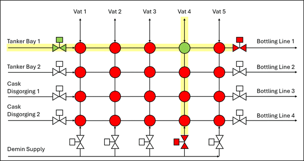
A valve block is a matrix of mix-proof valves used for automated routing of fluids between various sources and destinations. The size of the valve block depends on the number of sources and destinations – in Figure 1 a 4×5 valve block is shown as an example.
Mix-Proof Valves and Hygienic Separation
The mix-proof valves have two perpendicular flow paths through them: one at an upper level and one at a lower level. They are considered “mix-proof” as their double-seat design has two independent seals separated by a leakage chamber that allows two different fluids to be routed through the valve simultaneously without any cross contamination. If a seal does fail, the fluid will drain into the drip tray below via the leakage chamber, rather than contaminating the other fluid stream. It is typical to include a high-level switch on the drip tray to trip any ongoing transfer sequences if a leak is detected.
How Flow Routing Works (Actuated vs Unactuated)
When a mix-proof valve is not actuated, the two flow paths are independent and the fluid flows straight through the top level or bottom level. For example, the yellow flow path from Tanker Bay 1 in Figure 1 passes straight through each of the red (unactuated) valves until it meets a closed in-line isolation valve. When a mix-proof valve is actuated, the two levels are connected – see the green valve in Figure 1 which connects the horizontal path through the valve block with the vertical path. Again, the vertical path fills the column through the other unactuated mix-proof valves until it reaches a closed isolation valve.
Common Misconception: Does Actuation Divert Flow?
A common misconception is that actuating a mix-proof valve diverts the fluid from one level of the valve to the other, closing the straight-through route. This is not the case. The straight-through path on each level of the valve is always open; actuating the valve simply connects the two levels, allowing flow to be routed between rows and columns. The fluid therefore continues to pass straight through the valve until it reaches an isolation valve. This is illustrated in Figure 1, where the yellow fluid fills the row beyond the actuated green mix-proof valve until it meets the next in-line isolation valve. When the green valve is actuated, the internal connection between levels opens and the fluid fills the fourth column of the valve block, again stopping at the next closed in-line isolation valve.
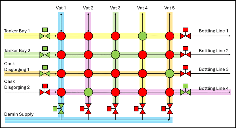
Why Valve Blocks Are Powerful: Multiple Simultaneous Transfer Routings
The advantage of a valve block becomes clear when multiple simultaneous routings are required. In Figure 2 there are five simultaneous sequences ongoing:
- Yellow – Tanker Bay 1 to Vat 4
- Green – Tanker Bay 2 to Vat 3
- Orange – Cask Disgorging 1 to Vat 5
- Magenta – Vat 2 to Bottling Line 4
- Blue – Demin Supply to Vat 1
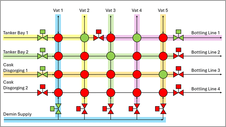
The number of different simultaneous operations that can go through a valve block can be increased by including additional isolation valves in-line. See Figure 3 where an isolation between the Vat 2 and Vat 3 columns allows transfers in from Tanker Bay 1 to Vats 1 or 2 whilst Vats 3 – 5 can transfer out to Bottling Line 1. This increased flexibility comes at the cost of additional footprint.
Applications
Valve blocks are suited to applications where there is a need for multiple transfer operations to be carried out simultaneously in a controlled manner. Their hygienic design makes them suited for food and beverage, dairy and brewing, pharmaceuticals and chemical processing. In the distilled spirits industry, they are commonly used at bottling plants and in larger distilleries.
Advantages
Compared to flow plates, which are the main alternative, valve blocks have the following advantages:
Automated Operation
Transfer sequences can be fully automated, reducing the risk of human error associated with the manual operation of a flow plate.
Dynamic Operation
Flow paths through the valve block can be changed automatically mid operation, e.g. allowing a vat to switch between recirculating and feeding forward as required. Changing a flow path on a flow plate is a manual task that can only be done once the route has been cleared of fluid.
Cross Contamination
The use of mix-proof valves in a valve block reduces the risk of cross contamination. Additionally, once all routes have been commissioned it would take a BPCS failure for a misrouting to occur. With a flow plate there is a risk of human error resulting in the source being connected to the wrong destination every operation.
Reduced Downtime
There is reduced downtime between operations compared to a flow plate, which requires the operator to detach and reattach hoses or swing bends between each transfer.
Disadvantages
Compared to flow plates, valve blocks have the following disadvantages:
Higher CAPEX
Valve blocks require more upfront investment than flow plates.
Footprint
The footprint of a valve block can often be larger than the footprint of a flow plate designed for the same operations.
More Parts to Fail
Compared to the simple design of a flow plate with manual valves, a valve block has more parts which could fail.
Harder to Understand
Flow plates are easy to understand just by looking at them, whilst there is a bit more complexity to the operating principle of a valve block, which can result in misconceptions about how they work.
Conclusion
Valve blocks provide a highly flexible, automated way to route fluids across multiple sources and destinations, especially where hygiene and simultaneous operations matter. By using mix-proof valves, they reduce cross-contamination risk and can cut downtime between transfers compared with manual flow plates—while also enabling dynamic, mid-operation route changes. The trade-off is higher upfront cost, a potentially larger footprint, and more components to maintain, so the best choice depends on how much operational flexibility and automation your plant needs versus CAPEX and space constraints.
Next Steps
If you’re considering a valve block or flow plate upgrade, speak to our Process Engineering Team. We’ll review your routing requirement and recommend the most practical option for your site – valve block, flow plate, or a hybrid that is based on safety, operability, footprint, and whole-life cost.