What is an instrument hook up drawing?
During the development of any project in detail design the process team will develop piping and instrumentation diagrams which will reflect the piping, engineering and instrumentation of any given process system. These drawings are representative of the engineering requirements and components required to achieve a safe and compliant operating process.
How instruments and valves are procured
Instrumentation and valves are key components of all P&IDs, the functionality between operating, monitoring and safety normally represented by specific symbols to ensure the reader can clearly understand the various plant interfaces.
The instruments and valves are normally procured via control data sheets which the instrument engineer will populate using the P&IDs, piping specifications and supporting input via the process team to ensure the conditions are understood correctly at any given point in the process. This information along with client specific standards then drives the instrument engineer’s decision as to the best technical option to ensure a suitable instrument or valve is procured.
What a hook-up drawing includes
The question now becomes – how do we turn an instrument or valve representing a control or safety loop on a P&ID into a physical installation at site? This is where the humble hook up drawing comes in.
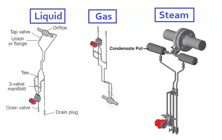
Instruments can be found in many different locations depending on the specific requirements of the process, for example, direct mounted to the pipework, remote mounted from the pipework via instrument tubing, direct mounted to vessels, remote mounted to pipework or vessels via diaphragm seals, or installed inline. The process medium is also a major consideration as a liquid, gas or steam application will look very different.
Designers and engineers drafting and checking project hook up drawings should consider the above factors to ensure instrument accuracy, repeatability and safety of personnel are adhered to especially on high or low pressure and temperature systems.
The image below details the general instrument positions to be considered in relation to the process tapping points when dealing with liquid, gas or steam process systems. Ensuring these positions are correct is essential to ensure each instrument operates as accurately and safely as possible for any given process application.
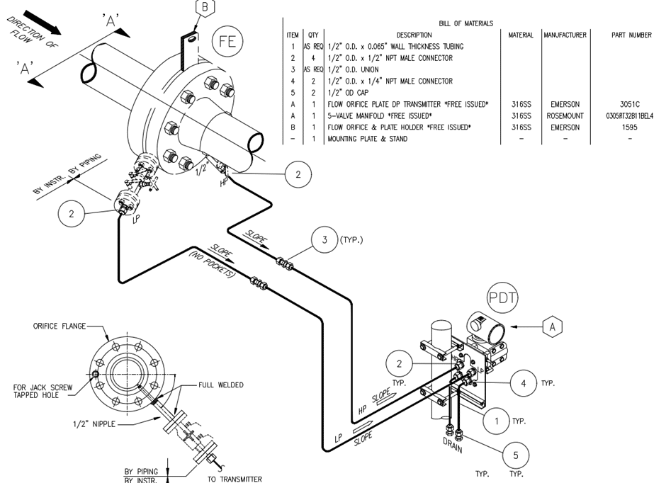
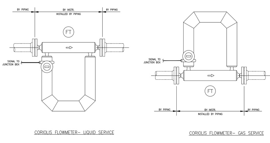
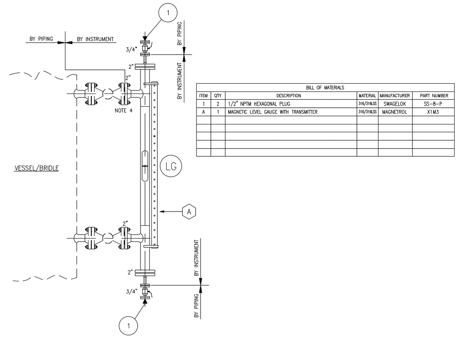
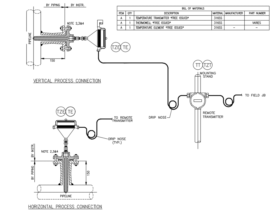
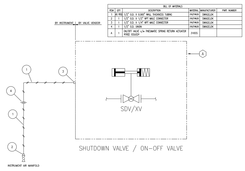
Common instrument hook-up drawing examples
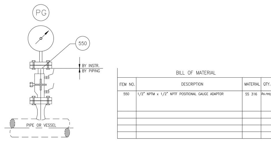
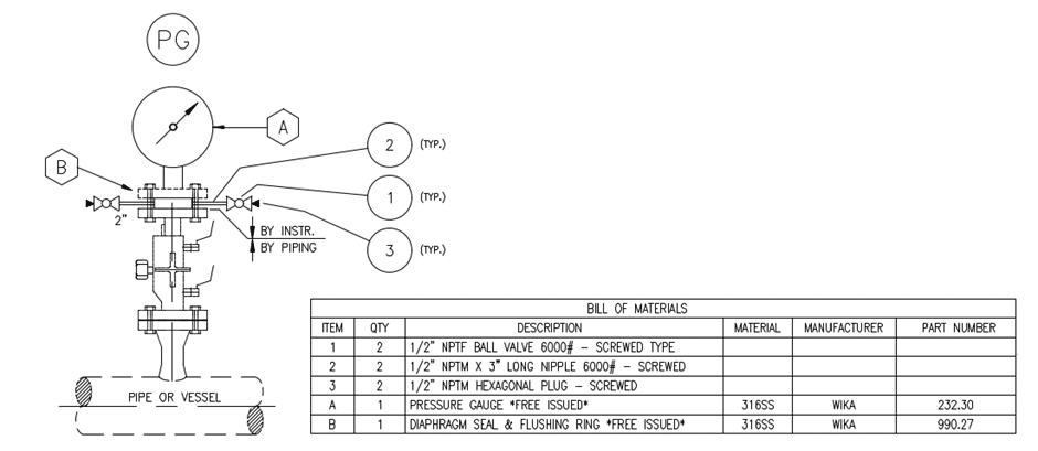
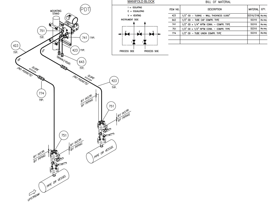
The hook up drawings detailed below show specific installation requirements around various typical arrangements that can be found on any given process. They do not cover every combination of hook up possible; the intention here is to show a general cross section of possible hook up options. The drawings show how an instrument should be installed with an associated bill of materials to ensure the appointed site contractor can ensure the P&ID and requirements of the process are safely brought to life.
Key checks before issuing for construction
There are many different methods around the installation of instruments and valves but hopefully the general cross section of methods shown above highlights the criticality of things to consider when producing hook up drawings.
Shown below are some salient points for any instrument engineer to consider when reviewing and approving hook up drawings:
- What is the process phase, gas, liquid or steam?
- Are there any process risks to the instrument or personnel from corrosive material, high or low temperature? (Eg: Consideration for use of diaphragm seals or additional instrument tubing length for temperature reduction)
- Is the instrument or valve ergonomically positioned for safety, maintenance and calibration?
- Is the drawing clear on material requirements and free issue boundary to enable the contractor to correctly supply and install the equipment?
- Have all client hook up standards been followed especially around expectations on instrument tubing gradients, 1:12 for example.
The above points in addition to good communication with the project piping and modelling team should ensure pipework tapping points are in the correct position in relation to each individual instrument’s functional requirement. This leads to a safe, efficient and reliable installation.
Contact our team to know more.